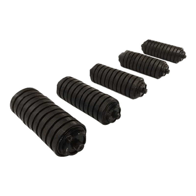
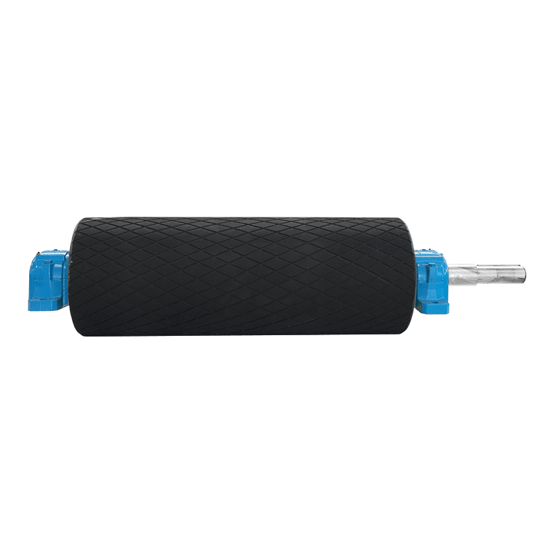
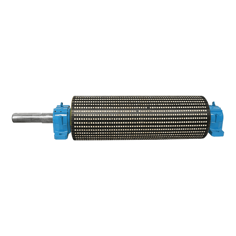
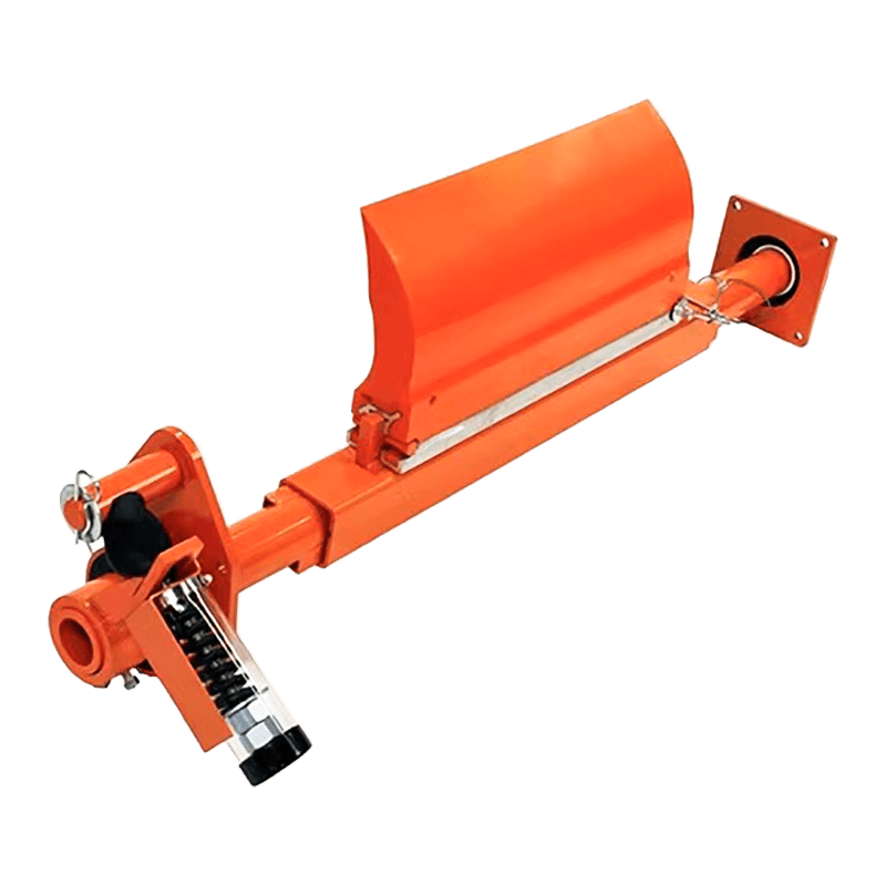
Belt conveyor flat roller: How does it work in the conveying system?
 2025.06.23
 Industry News
1. Core working principle: precise coordination of three functions
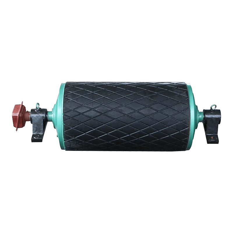
The belt conveyor flat roller realizes the three functions of support, guidance and self-alignment through exquisite mechanical design. Its working principle can be analyzed from three dimensions:
Load support mechanism
Upper roller group: usually 3-5 rollers are arranged in a groove shape, forming a 30-45° groove angle for the belt, increasing the transportation volume by 15-25%
Lower roller group: a single straight arrangement, bearing the belt return tension (usually 60-70% of the working section tension)
Dynamic load: a single roller can withstand 500-800kg impact load
Anti-deviation self-aligning system
Forward-leaning design (the axis is at an angle of 1-3° with the conveying direction)
The friction ring structure generates a lateral correction force (0.5-1.2N/m)
Asymmetric rubber ring wear indicator design
Rotational resistance control
Precision labyrinth seal (IP65 protection grade)
The filling amount of lithium-based grease accounts for 30-35% of the internal space
Rotational resistance coefficient ≤0.02
2. Usage specifications and maintenance points
Proper installation and maintenance are the key to ensuring the performance of flat rollers:
- Installation technical requirements
The height difference of rollers in the same group is ≤1mm (calibrated with a laser level)
Axial movement 0.5-1.0mm (retain thermal expansion margin)
Installation torque control (M10 bolt 15-20N·m)
- Daily inspection items
Weekly: Check the rotation flexibility (hand-turning resistance ≤1N·m)
Monthly: Measure the bearing temperature (ambient temperature +30℃ is the warning value)
Quarterly: Check the seal integrity (no visible grease leakage)
- Lubrication and maintenance specifications
Grease model: lithium-based grease NLGI 2#
Oil filling cycle: 6000 hours in normal environment, 3000 hours in dusty environment
Oil filling amount: 1/3 of the bearing space (excessive oil filling will cause overheating)
- Replacement judgment standard
Radial runout>1.5mm (measured 100mm from the end)
Rotation resistance>2.5N·m (measured by a special torque meter)
Bearing abnormal noise (noise value increased by more than 15dB)
- Safety precautions
Power must be cut off and locked during maintenance (LOTO procedure)
Use special disassembly and assembly tools when replacing (hammering is prohibited)
Discarded rollers are classified as metal waste
3. Precise installation specifications for flat rollers
The establishment of the benchmark of the frame and the legs is the prerequisite for the precise installation of flat rollers. The left and right deviations between the center line of the head and tail frames and the center line of the foundation must be ≤2mm, and the horizontality of the installation plane must be detected with an electronic level with an accuracy of 0.02mm/m, and the bubble deviation shall not exceed 0.5 grids. For the frame fixed with embedded iron, the contact surface gap should be checked with a feeler gauge, and any part should be ≤0.3mm, otherwise it needs to be leveled with stainless steel gaskets (temporary filling with wood chips or paper chips is prohibited). The verticality deviation of the legs should be less than 1mm/m, and the elevation difference of the top of all legs should be within 2mm, which can be fully detected by a laser leveler.
The positioning and spacing control of the roller group need to strictly follow the design parameters. The groove arrangement of the upper roller group should form a stable wrap angle of 30-45°, and the standard spacing should not be greater than 1200mm; in areas prone to impact such as below the guide trough, the spacing should be reduced to within 400mm; the transition zone of the convex arc section should be encrypted to 600mm spacing. During installation, a spacing positioning template can be made to greatly improve efficiency and ensure consistency. The arrangement spacing of the return flat rollers is usually ≤3000mm, and one set of lower centering rollers should be set for every 10 sets. Three sets of cleaning rollers should be installed continuously at the beginning of the return section to remove belt attachments. Pay special attention to the installation of the transition section. The distance from the first group of rollers to the head roller should be 1.3-1.5 times the normal spacing to avoid belt stress concentration.
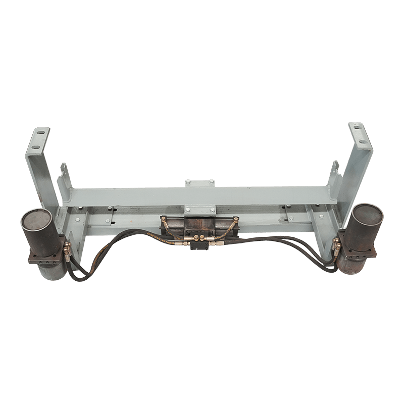
The precise realization of the self-aligning function depends on the precise control of the forward tilt angle. The standard forward tilt angle is 2°, and it is necessary to use an angle gauge or a digital inclinometer to check repeatedly during installation. The forward tilt direction must be correct: the side rollers of the trough roller group should tilt forward in the conveying direction, and the belt deviation is automatically corrected by the lateral friction force generated. For conveyors running in both directions, special designs such as rotating self-aligning rollers or hydraulic automatic deviation correction devices are required. After installation, it is necessary to manually simulate the belt deviation to verify whether the self-aligning mechanism can respond flexibly, and the swing resistance should be moderate (about 5-10N).
The bolt tightening process directly affects the long-term operation stability. The tightening of high-strength bolts (grade 8.8 and above) must be carried out in three stages: initial tightening (30% rated torque), re-tightening (80% torque) and final tightening (100% torque), and adjacent bolts should be tightened in diagonal order. Taking M12 bolts as an example, the final torque should reach 85-95N·m and be tested with a torque wrench. The spring washer must be completely flattened, and the opening gap ≤ half of the gasket thickness (for example, if the M12 gasket is 3.1mm thick, the opening m ≤ 1.55mm). The anti-loosening mark is painted as follows: Bolts above M8 are marked with red and black double lines, with a line width of 1.5-2mm and a spacing of 2-3mm; the self-checking black line extends from the side of the nut to the surface of the substrate, and the mutual check is drawn in parallel with the red line. This strict tightening process can reduce the risk of loosening by 80%.

 English
  русский
 Español


